Driveshaft Manufacturing
Our driveshaft manufacturing process is flexible, adapting to the production phase and specific industry requirements of our customers. During the prototype phase of new chassis or industrial designs, driveshafts are often oversimplified, but we’re here to ensure precision and reliability.
Feel free to contact us and share your prints or specifications. We’d be delighted to partner with you on your next build.
Every new build comes with variables that can introduce or alter forces impacting driveshaft suitability. These forces can reduce bearing life and lead to failures—not only in the shaft itself but also in connected components.
To help mitigate these risks, our team will assist your engineers with series selection, angle calculations, and critical speed constraints.
Below, you'll find a series of calculations and tools designed to support your engineering team in setting up your driveshaft system.
Technical Requirements
Determining the appropriate driveshaft for your specific chassis application requires several calculations, primarily focused on torque and RPM.
Below, we provide an explanation of the torque calculation requirements to guide your process.
Driveshaft Torque Requirements & Series Selection
Selecting the appropriate driveshaft series is essential for any system, balancing torque and bearing life requirements against potential output loss.
Maximum Torque in Low Gear
The primary calculation for driveshaft selection in a chassis involves determining the maximum torque applied to the front of the driveshaft. This begins with the gross engine torque and factors in all gear ratios that amplify or reduce the force. The result is then adjusted for the efficiency of each component connected to the front of the system.
Wheel Slip Torque
The wheel slip torque calculation determines the torque needed for the vehicle's wheels to slip. This calculation is applicable only for road use where the payload does not exceed the gross combined weight.
For off-highway and specialty applications, other factors may reduce or eliminate wheel slip, making the maximum torque in low gear the appropriate threshold for series selection.
For detailed application guidelines and calculations, please refer to resources from Dana and Cummins – Meritor .
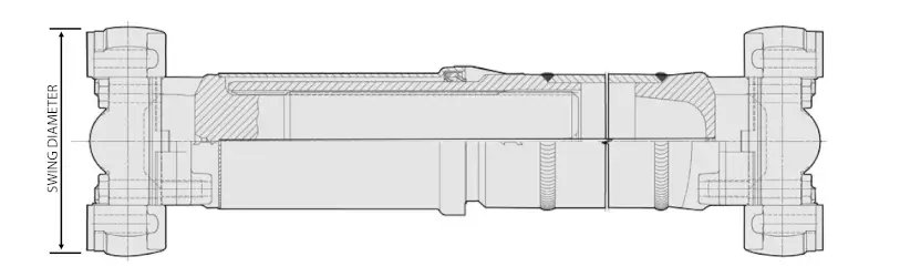
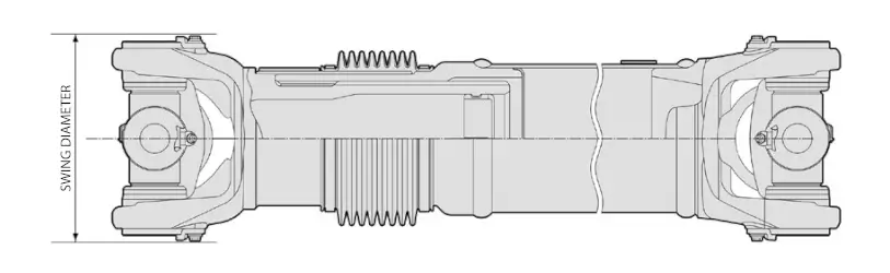
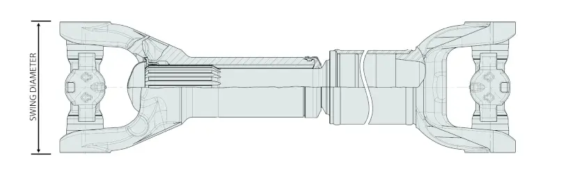
Driveshaft System Envelope & Length Vs. Number of Driveshafts
After determining the torque requirements for the driveshaft, the next step is to assess any clearance constraints that could affect maximum swing or tubing diameter.
Ensuring sufficient clearance is critical to accommodate system movement under load and within the suspension's arc.
Series Selection
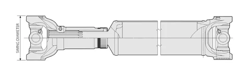
| Series | Functional Torque Limit | Swing Diameter1 | Tube Diameter2 | |||
|---|---|---|---|---|---|---|
| lb-ft | Nm | in | mm | min (in) | max (in) | |
| 1310 | 1,719 | 2,330 | 4.00 | 101.6 | 1.250 | 4.000 |
| 1330 | 1,991 | 2,700 | 4.56 | 115.8 | 2.000 | 5.000 |
| 1350 | 2,876 | 3,900 | 4.56 | 115.8 | 2.000 | 5.000 |
| 1410 | 3,467 | 4,700 | 4.94 | 125.5 | 2.500 | 5.000 |
| 1480 | 4,057 | 5,500 | 5.75 | 146.1 | 3.000 | 5.000 |
| 1550 | 5,163 | 7,000 | 6.00 | 152.4 | 3.500 | 4.000 |
| 1610 | 6,000 | 8,135 | 7.00 | 177.7 | 3.500 | 4.000 |
| 1710 | 11,358 | 15,400 | 7.89 | 200.2 | 3.500 | 4.500 |
| 1760 | 12,000 | 16,270 | 8.40 | 213.2 | 4.095 | 4.095 |
| 1810 | 16,500 | 22,370 | 9.10 | 231.0 | 4.590 | 4.590 |
1 Swing diameter clears yoke by 0.06 in (1.5 mm)
2 Tube thickness diameter can modify the functional torque limit.
| Series | Functional Torque Limit | Swing Diameter1 | Tub Diameter2 | |||
|---|---|---|---|---|---|---|
| lb-ft | Nm | in | mm | min (in) | max (in) | |
| 5C | 4,130 | 5,600 | 4.85 | 123.0 | 2.500 | 3.543 |
| 6C | 5,310 | 7,200 | 5.91 | 150.0 | 2.750 | 3.543 |
| 7C | 7,892 | 10,700 | 6.23 | 158.0 | 3.000 | 4.000 |
| 8C | 11,432 | 15,500 | 8.51 | 216.0 | 3.500 | 4.000 |
| 8.5C | 14,973 | 20,300 | 6.90 | 175.0 | 3.543 | 4.724 |
| 9C | 20,209 | 27,400 | 8.79 | 223.0 | 4.528 | 4.724 |
| 10C | 29,281 | 39,700 | 8.87 | 225.0 | 5.000 | 5.000 |
| 11C | 30,683 | 41,600 | 9.26 | 235.0 | 5.669 | 5.669 |
| 12C | 45,876 | 62,200 | 11.86 | 301.0 | 6.299 | 6.299 |
| 12.5C | 46,466 | 63,000 | 11.62 | 295.0 | 6.299 | 6.299 |
1 Swing diameter clears yoke by 0.06 in (1.5 mm)
2 Tube thickness diameter can modify the functional torque limit.
| Series | Functional Torque Limit | Swing Diameter1 | Tube Diameter2 | |||
|---|---|---|---|---|---|---|
| lb-ft | Nm | in | mm | min (in) | max (in) | |
| SPL55 | 4,057 | 5,500 | 5.32 | 134.9 | 3.000 | 4.000 |
| SPL70 | 5,163 | 7,000 | 6.00 | 152.4 | 3.500 | 4.000 |
| SPL100 | 7,376 | 10,000 | 6.07 | 154.0 | 4.000 | 4.000 |
| SPL140 | 10,326 | 14,000 | 6.30 | 160.0 | 4.331 | 4.560 |
| SPL170 | 12,539 | 17,000 | 7.60 | 193.0 | 4.500 | 4.961 |
| SPL250 | 16,595 | 22,500 | 7.60 | 193.0 | 4.670 | 5.197 |
| SPL350 | 22,127 | 30,000 | 8.12 | 206.0 | 5.590 | 5.590 |
1 Swing diameter clears yoke by 0.06 in (1.5 mm)
2 Tube thickness diameter can modify the functional torque limit.
| Series | Functional Torque Limit | Swing Diameter1 | Tube Diameter2 | |||
|---|---|---|---|---|---|---|
| lb-ft | Nm | in | mm | min (in) | max (in) | |
| RPL10 | 6,000 | 8,135 | 7.01 | 177.8 | 4.000 | 4.000 |
| RPL14 | 10,000 | 13,558 | 7.81 | 198.1 | 4.095 | 4.095 |
| RPL20 | 12,000 | 16,270 | 7.81 | 198.1 | 4.000 | 4.095 |
| RPL25 | 17,200 | 23,320 | 9.11 | 231.1 | 4.590 | 4.590 |
| RPL25SD | 18,500 | 25,082 | 9.11 | 231.1 | 4.690 | 4.690 |
| RPL35 | 21,600 | 29,286 | 8.10 | 205.7 | 4.690 | 5.204 |
| RPL35SD | 25,815 | 35,000 | 8.10 | 205.7 | 5.204 | 5.204 |
1 Swing diameter clears yoke by 0.06 in (1.5 mm)
2 Tube thickness diameter can modify the functional torque limit.
Critical Speed RPM Calculation
Critical Speed: The RPM at which the driveshaft reaches its natural frequency. This is calculated using the modulus of the driveshaft material, tube diameter, and length. (For example, longer driveshafts have lower critical speeds.)
Adjusted Critical Speed: This adjusts the critical speed to reflect the maximum safe operating speed, ensuring safety and accommodating shaft movement.
For precise calculations, reference Dana's Driveshaft Safe Operating RPM Calculator to verify the maximum driveshaft length suitable for your application. This tool will also help determine the required number of driveshafts for your system.
Driveshaft Angle Calculations
The universal joints in a driveshaft are engineered to enable rotation at an angle relative to the connected components.
- Optimal Operating Angle: 1.0°–3.0°
- Minimum Angle: 0.5°
- Maximum Angle: 5.0°
Operating beyond 3.0° can significantly reduce the lifespan of the universal joint. Refer to the diagram below for guidance on calculating the coupling angle.
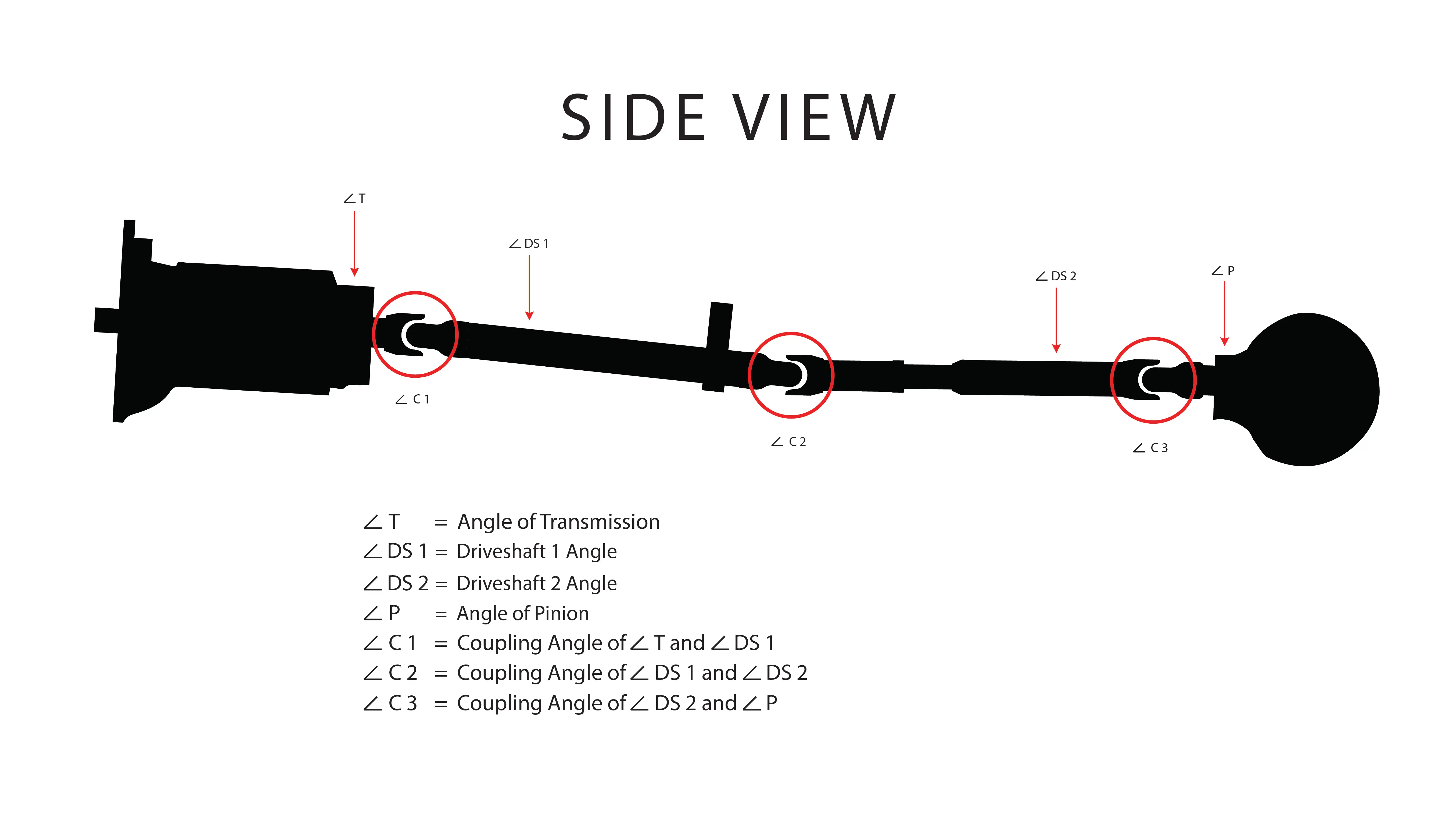
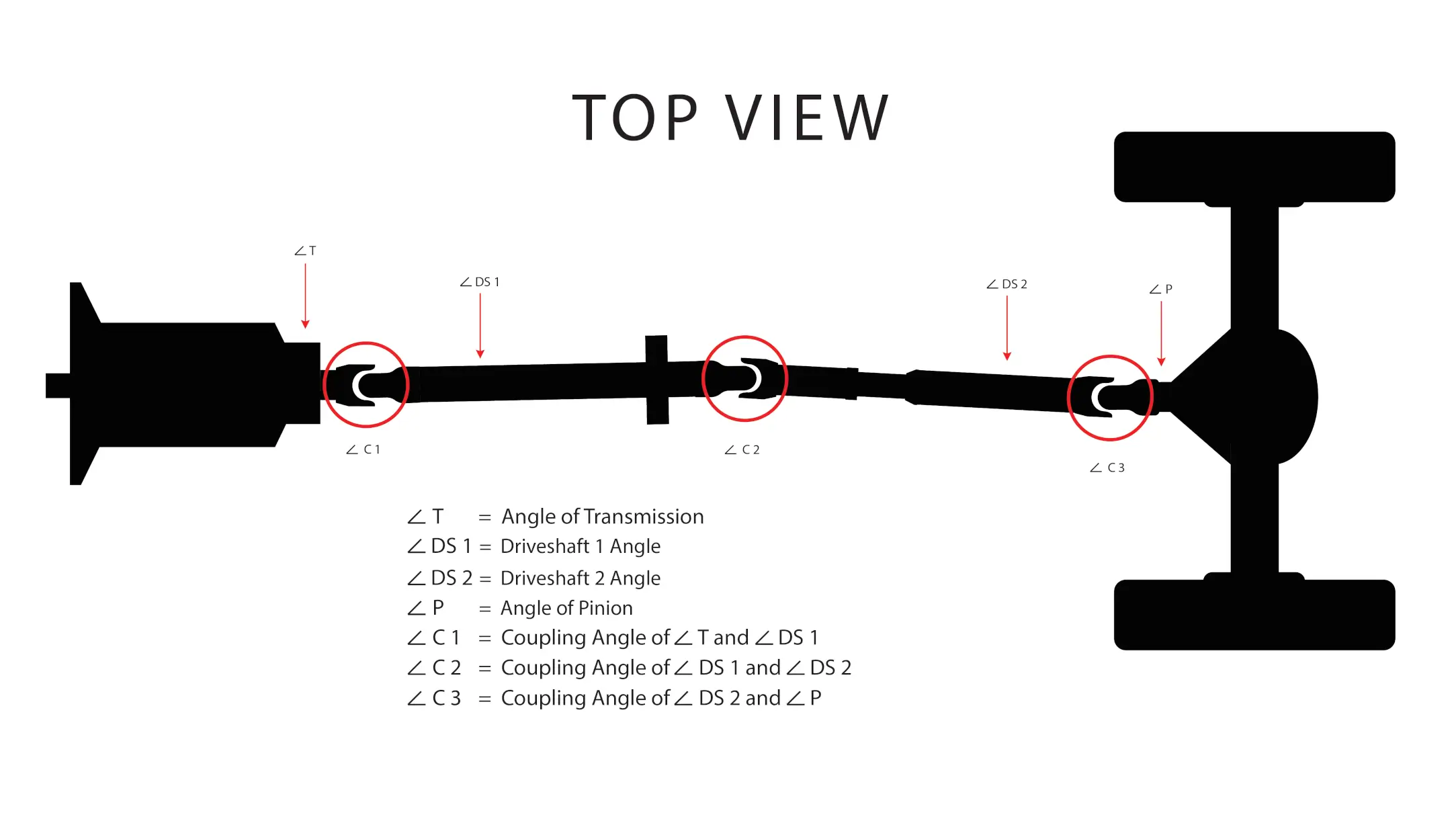
To determine the U-joint coupling angle:
- If the angles of the components are in the same direction, subtract one angle from the other.
- If the angles are in opposite directions, add the angles together.
This calculation provides the U-joint coupling angle.
Below is an example of a driveline system with its corresponding coupling angles.
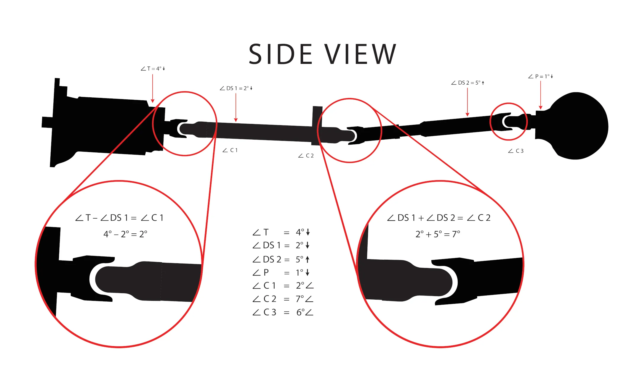
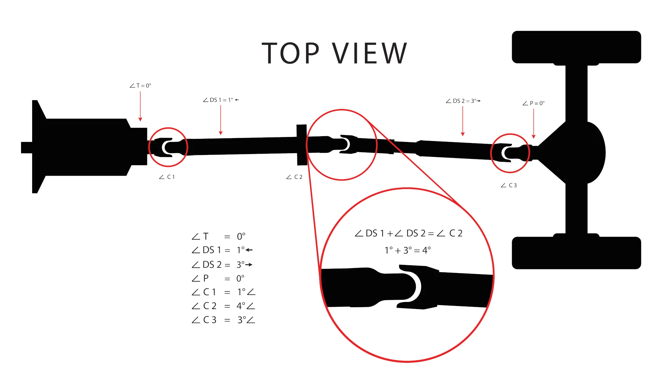
If the examples above refer to the same vehicle, the coupling angles from the side view and top view must be combined, as illustrated below.
| 0S | 0T | 0C | |
|---|---|---|---|
| ∡C1 | 2.0 | 1.0 | 2.2 |
| ∡C2 | 7.0 | 4.0 | 8.1 |
| ∡C3 | 6.0 | 3.0 | 6.7 |
In the example above, 0C references the combined coupling angles for the setup. ∡C2 & ∡C3 exceed the maximum allowable angles, this would significantly reduce bearing life and based on the application could cause excess vibration and/or system failure.
There are additional calculations and considerations in the Dana and Cummins – Meritor application guidelines.
At DCJ Inc, we prioritize quality by using only high-grade components from trusted manufacturers. Our production parts are sourced directly from leading driveshaft component suppliers worldwide, including well-known and reliable brands such as: