How to Measure a Driveshaft
For an accurate driveshaft measurement, ensure the vehicle's weight is resting on its axles. Measuring while the vehicle is on a lift with the axles suspended will result in an incorrect measurement.
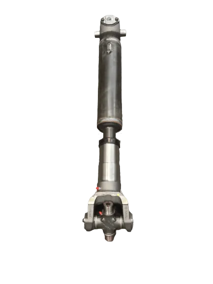
Single Piece Driveshaft
To measure a single-piece driveshaft, begin by identifying the connection points of the shaft. Start from the transmission side and measure to the corresponding point.
- Transmission Input Spline:
Measure from the end of the splined shaft exiting the transmission sleeve. - Pinion Yoke:
Locate the surface where U-bolts or bearing strap bolts enter the yoke.
Mark the centerline of the U-joint cap and measure from this flat surface. - Flange:
Measure from the flat surface at the end of the flange.
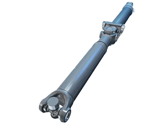
Multi-Piece Driveshaft
Similar to a single-piece driveshaft, measuring a multi-piece shaft begins by identifying the connection points.
- Measure the length from the transmission connection point to the center of the bolt hole for the carrier bearing.
- From the same carrier bearing point, measure to either:
The next carrier bearing bolt hole, or the end connection point, depending on the number of driveshaft sections.
Vibration Analysis
Start by asking: Has anything changed recently? Consider new tires, shocks, lift kits, motor mounts, or other modifications.
- Remove the driveshaft.
- Inspect the U-joints: Move them in all directions. If they feel loose or gritty, they need replacement.
- Test the carrier bearing: Spin it to ensure it rotates smoothly.
- Examine the driveshaft tube for visible damage.
How to Remove and Install Universal Joints
Outside Snap Ring Universal Joints Removal
To remove snap ring-style U-joints, start by removing the snap rings, which may be either internal or external.
- Use a specialized tool or position the opposing cross on a heavy-duty vice.
- Strike the curved portion of the yoke between the cap opening and the tube.
- This action will drive the cap upward and out of the yoke.
- Repeat the process for all caps.
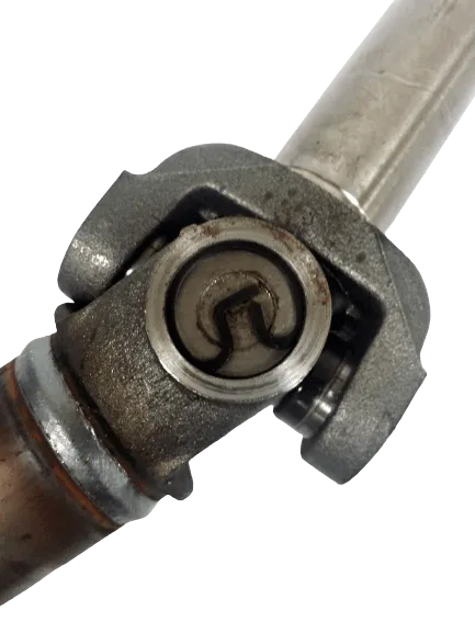
Nylon-Injected Universal Joint Removal
Some driveshafts are manufactured with nylon injected into the yoke to secure the U-joint caps. This nylon must be removed before the U-joint can be disassembled.
- Look for a visible plug around the cap area, as shown in the accompanying picture.
- If present, this driveshaft should be brought to a qualified technician for removal.
Identifying Nylon Retention:
- The generally accepted method is to heat the yoke around the injection plug.
- As the nylon heats, pressure builds and ejects the plug, releasing the retention mechanism.
Removal Process:
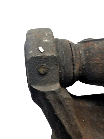
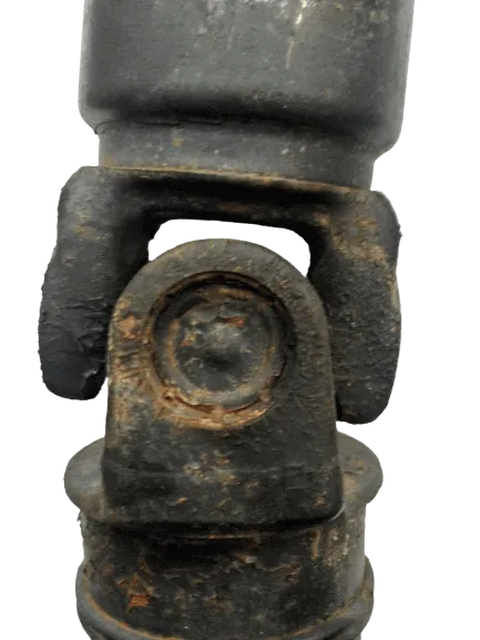
Staked-In Universal Joint Removal
Some driveshafts are equipped with staked-in U-joints from the OEM. These joints are secured by a portion of the yoke pressed over the cap, as shown in the accompanying picture. These are often considered non-serviceable by many.
- Press Out the U-Joint Caps:
Push the caps through the stakes in both directions. - Grind the Yoke:
Smooth the internal surface of the yoke to accommodate the replacement U-joint caps. - Prepare the Yoke:
Clean the ear of the yoke and ensure the surface is properly finished to fit the inside snap rings correctly.
Inspect the yoke for damagdive and clean the areas where the snap rings will seat.
Installing a New Universal Joint
- Align Grease Fittings:
If the U-joint includes grease fittings, align them for easier maintenance.
Apply a small amount of approved grease inside each cap to secure the needle bearings and lubricate the trunnions and cross. - Position the Cross and Cap:
Align the cross and cap, ensuring part of the cross is seated in the cap to prevent needle bearings from dislodging.
Press the cap into the yoke carefully to avoid binding or dropping the needles. - Use Specialized Tools:
For best results, use a specialized U-joint tool. Alternatively, a heavy-duty vice, arbor press, or C-clamp can be used. - Install Snap Rings:
Press the first cap far enough to insert the snap ring securely.
Ensure the snap ring is properly seated; failure to do so may cause the cap to slide out during opposing cap installation.
For caps requiring external snap rings:
Use a punch or socket with a vice to press the cap past the groove.
Insert the snap ring using needle-nose pliers.
Press the opposing cap into place and install the second snap ring. - Troubleshooting Snap Ring Installation:
If the second snap ring cannot be seated:
A needle may have fallen into the cap.
The yoke could be sprung or the snap ring groove damaged.
If the groove is damaged, rotate the snap ring so the opening aligns with the damaged area. - Finalize Installation:
If the U-joint feels stiff after installation, strike the base of the yoke lightly to free the joint.